– Atmega8 programming, part 1: the backstory and how to not-blink an LED
1678 words, ~8 minutes
This post has, for the time being, unsatisfying conclusion. You have been warned.
Last Sunday I was planning to take a break from programming. Maybe start solving one of those 1500 pieces jigsaw puzzles. Unfortunately my dad did not realize it, and started throwing vaguely formulated project ideas:
You know what would be cool? If you could somehow put Spotify and that new cool Polish internet radio and maybe some other internet radios in my old boombox. Ooooh, and if you could make it so when you turn the frequency knob to change the station, there’s noise between them.
Wait, what?
Now, we all know this is going to end up just like all my side projects thus far. Not very close to being done. But you know, that’s fine, that’s a learning experience.
I have sparse electronic knowledge, and close to none electric knowledge, but please bear with me.
So, how can we do this?
First of all, you need something to connect to Spotify (and more generally, the internet). A Raspberry Pi would make that easy, and I have a 2B model on my shelf just lying there doing nothing. I also have a Zero model, but it’s a bit less effortless to connect it to the internet. And more importantly, it doesn’t have a 3.5mm audio jack. All of this can be worked around, but I don’t believe you should put extreme amounts of work into prototypes.
A Raspberry Pi also has enough pins to plug in a lot of electronic things like buttons, switches, knobs— wait a second, buttons and switches are easy because they’re binary, either 0 or 1, digital inputs. Knobs however take a continuous value somewhere in range from where they start to where they end. A Raspberry Pi alone cannot read analog input. You need an ADC (analog-to-digital converter) for that.
From what I understand, an ADC measures voltage on a pin and compares it to some reference voltage, and turns the ratio into a number that can be read by a microcontroller. Now, I don’t have any ADC in my drawer, but I have something that has one.
A bit of backstory
Back in high school days I was kind of part of a robotics club. It was great fun, I got to hang out with my nerd friends, even though back then I didn’t understand quite a lot that was happening.
The greater goal of the robotics club was to take part in a maze solving competition, where you build a robot within certain size constraints and it has to solve a maze. Unfortunately, Polish school system is rather hostile to extracurricular efforts which are not directly related to passing exams or getting into universities. I mean, rather than directly hostile, it outcompetes these for resources.
But what the club did manage to accomplish was give me a rough course of AVR programming. AVR is a family of 8-bit microcontrollers. I think the Wikipedia page knows much more about them than I do, and either way, if you got here by googling “atmega8 blink”, this is not what you’re here for.
This is where the Atmega8 comes in
The microcontroller we learnt to use at the robotics club was Atmega8. I still have my development board, made by a company from Shenzen whose website appears to be dead. Fortunately, I found a clear photo of it on the Wayback Machine:

It is powered by mini-USB (as opposed to micro-USB in last decade’s smartphones) on the right, but if you plug the programmer in (through the big socket labeled ISP on the left), that’s gonna power it too. It’s probably good to remember about that.
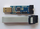
For programming I have a USBASP, which is an open hardware device that’s pretty well supported by open source tools. In particular, I have a version manufactured by the same Chinese company, which looks like this in potato quality:
How do I blink an LED with that?
Well, first you need an LED. Unfortunately the LEDs I had in high school have disappeared somewhere. However, I think I know what code to write.
Let’s assume that you’re plugging your LED (with a resistor, because you don’t want to burn it, but I can’t help you with that, because I’m not good at it) to pin B2 on the board and to GND (ground).
Let’s write some C code! I’ll explain it inline with comments.
|
|
Shorter version without comments and redundant operations here:
|
|
Wait, you never taught me to compile things!
Oh, that’s true. Let’s get that done.
For my own sake, I’m gonna assume you’re using Linux. USBASP is just so so annoying to use on Windows, because the driver isn’t signed, and anyway I’m not a big fan of Windows. I’ve actually done all this recent AVR programming on my Raspberry Pi.
If you’re using Debian or Ubuntu or something that’s close enough to either of the two, you’ll want to install the following packages:
avr-libc, which contains the standard C library for AVR;gcc-avr, which is the GNU C Compiler for AVR;binutils-avr, which contains tools for operating on AVR programs,avrdude, which is the programming tool for AVR.
If you’re using something else, or if I got one of these wrong, it’s probably
called roughly the same, you may just need to flip the order (like, avr-gcc
instead of gcc-avr).
Then, there are three steps to getting your program onto your Atmega8:
-
Compile it. Assuming you wrote your program in
led.c, you’ll want to run something like this:avr-gcc -mmcu=atmega8 -Os -Werror -Wall -Wextra -o led.bin led.c-mmcu=atmega8specifies that theMachine, theMicroControllerUnit we are compiling for, is an Atmega8. This is important because there are differences between various AVRs regarding where registers are mapped or what operations are available.-Osmeans optimizing for smallest possible size of the resulting program.-Wall -Wextraturns on a lot of compiler warnings and checks. If you’re not adding these while writing any C program, you may want to start doing that.-Werrorturns all compiler warnings into errors. This is probably not so important when you’re compiling by hand, but when you have a script or a Makefile that compiles your program and then immediately flashes it to the device, this will usually stop the script if there are warnings. It can save you time.-o led.binsaves the result toled.bin.
-
Convert it to Intel Hex. By default
led.binwill be an ELF file for AVR architecture, which might not be something you want to flash. I mean, I never tried, this is something I was taught to do in high school, let me know if that’s changed.avr-objcopy -O ihex led.bin led.hex-O ihexflag sets output format to Intel Hex, then the first argument is source file and the second argument is destination. -
Flash it to the device:
avrdude -c usbasp -p m8 -U flash:w:led.hex-c usbasptells avrdude that the programmer device you’re using is USBASP. If you want to list all available options, use-c refjeiorfjeriofier, and it will tell you it’s not a valid option and what the valid options are.-p m8specifies that the target device is an Atmega8. Like in the first option, you can punch your keyboard instead of typing m8 to get a list of possible targets, but the programmer device has to be correct for that to work.-U flash:w:led.hexchooses the memory operation. We want to operate on flash memory, we want to write to it, and what we want to write isled.hex.
If avrdude doesn’t want to run because of lacking permissions or because it can’t find the programmer, your system user might not have direct access to USB devices such as the programmer. One way to deal with it is to run avrdude with
sudo– I trust that you have received the usual lecture from the local System Administrator. You could also teach udev to let you access the programmer, but this is kinda out of the massive scope here.
So if you perform all these steps, and if all goes right, your microcontroller will be flashed with a program that… doesn’t quite blink the LED, does it? I’m afraid that I tricked you and what the program does is just turn the LED on. You’ll have to wait for the blinking part until after I’ve eaten lunch.